


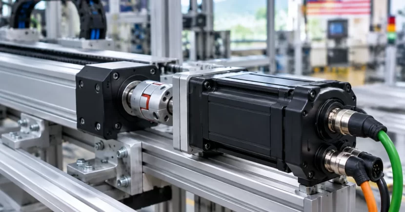
When an automation axis feels underpowered (stalls, overheats, poor following) or overpowered (overshoot, hunting, unnecessary cost), the root cause is often servo sizing. A solid selection starts with the motion profile and mechanics, then translates them into required speed, continuous/RMS torque, peak torque, and a controllable inertia ratio.
This tutorial is for OEM machine builders and system integrators specifying Servo Motor Malaysia solutions for pick-and-place, indexing tables, and packaging machines. Use it as a practical worksheet before committing to a motor frame size, gearbox, or coupling.
Step 1: Define the axis motion (the part most people skip)
Servo sizing is only as accurate as your cycle definition. Most real axes accelerate, cruise briefly, decelerate, then dwell. Start by writing down the actual cycle.
1. Capture a simple cycle table
- Move distance (linear mm or rotary degrees)
- Move time (s)
- Dwell time (s), if any
- Accel/decel profile (trapezoidal or S-curve)
- Cycles per minute / duty pattern (continuous vs intermittent)
Why it matters: RMS (heating) torque depends on time spent accelerating vs cruising vs dwelling. Pick-and-place often has high peaks but low average; many packaging axes run long duty cycles where RMS becomes the limiter.
2. Choose a conservative acceleration model
If you don’t have the final cam yet, start with a trapezoid for first-pass sizing. An S-curve (jerk-limited) can reduce vibration and sometimes peak torque, but don’t depend on it to rescue an undersized motor.
Step 2: Convert the load to motor speed (linear and rotary)
Convert required axis speed to motor rpm through the mechanical transmission, and avoid designing an axis that lives at the motor’s absolute max rpm.
A) Linear axis with ballscrew
- Screw speed (rev/s) = linear speed (mm/s) ÷ screw lead L (mm/rev)
- Motor speed = screw speed × ratio (if belt/gearbox is used)
Tip: selecting a lead that keeps typical operation mid-range often improves noise, efficiency, and tuning margin.
B) Linear axis with belt/pulley
- Axis speed (m/s) = pulley circumference (πD) × pulley rev/s
- Motor speed = pulley speed × ratio (motor:pulley)
Belts are common on gantries; belt elasticity can reduce stiffness. Ratio selection affects reflected inertia and achievable control bandwidth.
C) Rotary axis / indexing table
- Direct drive: motor speed = table speed
- With gearbox: motor speed = table speed × ratio
Practical note: gearboxes often improve settling by reducing reflected load inertia and multiplying torque, but backlash and stiffness must match your positioning tolerance.
Step 3: Estimate torque components (acceleration, friction, gravity, process load)
Torque demand is the sum of inertia-driven acceleration, friction/losses, gravity (if applicable), and any process forces. Check both peak torque (instant capability) and RMS torque (thermal capability).
1) Acceleration torque (inertia-driven)
Tacc = Jtotal × α
- Jtotal: total inertia reflected to the motor shaft (kg·m²)
- α: angular acceleration (rad/s²)
This is why Step 4 is central: fast moves can demand high torque even with low mass.
2) Friction torque and efficiency
Friction can be significant (guides, seals, reducers, belts). If you don’t have measured values, estimate conservatively and include efficiency losses so the motor is not sized “on paper only.” Add margin for lubrication, temperature, and wear.
3) Gravity torque (vertical axes)
For Z-axes, consider:
- Holding/standstill torque to prevent drift
- Upward torque (gravity + acceleration)
- Downward control (regen and controlled decel)
If the axis must be safe on power loss, align servo selection with a brake or counterbalance strategy.
4) Process torque / external load
Sealing, cutting, pushing, and intermittent contact loads should be added as force/torque. If impulsive, verify motor/drive peak torque and coupling capacity to avoid slip or shock damage.
Step 4: Calculate reflected inertia and check the inertia ratio
Inertia mismatch commonly causes oscillation, poor settling, and difficult tuning. You don’t need a perfect match, but you do want a ratio the drive can control comfortably.
1) Reflect everything to the motor
- Motor rotor inertia (datasheet)
- Coupling/pulley/gearbox input inertia
- Load inertia reflected through the ratio
- Equivalent inertia of linear masses converted through screw lead or pulley radius
Gear ratio effect: reflected inertia through a reducer scales roughly with the square of the ratio. This is why adding ratio can be more effective than simply choosing a larger motor.
2) Linear mass to rotary inertia (concept)
Any linear moving mass becomes an equivalent rotary inertia at the motor shaft based on your mechanical conversion and ratio. Vendor tools are helpful, but sanity-check inputs (lead/diameter, ratio direction, efficiency).
3) What to do if the ratio is high
- Add or increase gearbox/belt ratio to reduce reflected load inertia
- Move to a larger motor (more torque and rotor inertia)
- Reduce moving mass or required acceleration
- Increase mechanical stiffness (couplings, belts, mounting)
Packaging reality: slightly reducing acceleration can improve throughput if it cuts settling time caused by vibration.
Step 5: Select motor, drive, and mechanics as one system (with safety margin)
Shortlist motors/drives using speed, peak torque, RMS torque, and inertia ratio, then verify the full system: motor + encoder + drive + gearbox/belt/screw + coupling.
1) Check speed limits with margin
- Voltage drops and drive limits
- Future cycle-time increases
- Tuning headroom (bandwidth often degrades at very high speed)
2) Separate peak torque from RMS torque
- Peak torque: acceleration, fast decel, and process spikes
- RMS torque: heating over the duty cycle
If peak is fine but RMS is high, the axis may pass a short test yet overheat in production—especially on continuous packaging lines.
3) Decide whether you need a gearbox
Gearboxes are useful not only for low-speed/high-torque. They can reduce reflected inertia, place the motor in a better speed range, and improve effective resolution at the load. For auxiliary axes around servo stations (conveyors, feeders), geared solutions like helical gear motors or helical bevel geared motors can keep the overall machine robust and cost-effective.
4) Couplings, backlash, and stiffness
Mechanical compliance can dominate performance. Check:
- Torsional stiffness (critical for indexing)
- Backlash vs tolerance
- Belt stretch and tensioning method
- Mounting rigidity (plate/bracket flex becomes a spring in the loop)
If you see overshoot or long settling, the fix is often stiffness/backlash or ratio—not simply a bigger motor.
5) Protect the drivetrain during starts and jams
Plan torque limits and safe start/stop behavior, especially on higher-inertia systems. Even though hydraulic couplings (e.g., Transfluid couplings) are usually for non-servo drives, the same principle applies: combine control-layer limits with practical mechanical protection so jams don’t destroy gear teeth, couplings, or keys.
Step 6: Validate with a quick spreadsheet test (and plan commissioning checks)
Before ordering hardware, run a quick validation pass to catch major mistakes and confirm you have thermal and tuning margin.
A practical validation checklist
- Re-check units (mm vs m, rpm vs rad/s, N vs kgf).
- Confirm ratio direction (higher ratio increases load torque but increases motor speed).
- Compute peak and RMS torque for the full duty cycle, including dwells.
- Check inertia ratio and whether the drive can tune it stably.
- Check regeneration for fast decels (braking resistor/regen capacity).
- Add margin for friction change, product variation, and future tuning.
Commissioning measurements to confirm assumptions
- Motor current/torque trend over cycles (RMS reality check)
- Position error during accel/decel (tuning headroom)
- Temperature rise during continuous running (thermal margin)
- Stop accuracy and settling time (stiffness/backlash assumptions)
Conclusion: A repeatable servo sizing workflow for real machines
Servo sizing for pick-and-place, indexing tables, and packaging machines works best as a repeatable workflow: define the motion, convert it to motor speed, build torque from inertia + friction + gravity + process load, then manage inertia ratio with ratio choice and mechanical stiffness (not guesswork based on motor power alone).
With a documented cycle profile and calculated peak/RMS torque plus inertia ratio, supplier discussions become faster and quotes become more accurate. For related drivetrain selection across the rest of the machine, see Common Gear Motor Malaysia and Why Helical Bevel Gear Reducers Are Ideal For Heavy Duty Applications In Malaysia.
Frequently Asked Questions
What information do I need before sizing a servo for a pick-and-place axis?
At minimum: move distance, move time, accel/decel style (trapezoid or S-curve), duty cycle (cycles/min and dwell time), mechanical transmission details (ballscrew lead or pulley diameter and belt ratio), moving mass, and any external process forces. With these, you can estimate required speed, peak torque, RMS torque, and the reflected inertia ratio.
How do I decide between direct drive and using a gearbox for an indexing table?
Use direct drive when you need zero backlash and your table inertia and acceleration are manageable within motor torque and inertia limits. Use a gearbox when you need higher torque, better control of reflected inertia, or improved stability/settling—provided you can tolerate and manage backlash (choose low-backlash gear solutions and ensure mechanical stiffness).
What is the difference between peak torque and RMS torque in servo sizing?
Peak torque is the short-duration torque needed during acceleration, rapid deceleration, or load spikes. RMS torque is the time-weighted average torque over the full cycle and is what drives motor heating. A servo can pass a brief peak event but still overheat in production if RMS torque is too high for continuous operation.
Why does my servo oscillate even though the motor torque seems sufficient?
Oscillation is often caused by inertia mismatch, backlash, belt stretch, flexible mounting plates, or a coupling that is too compliant. These mechanical issues reduce system stiffness and limit achievable control gains. Improving rigidity, changing ratio (often adding a gearbox), or reducing reflected inertia can stabilize tuning more effectively than simply increasing motor power.
Can I use a gear motor instead of a servo motor for packaging or indexing applications?
For constant-speed or simple on/off motion (conveyors, feeders, many auxiliary drives), a gear motor can be a cost-effective and robust choice. For precise positioning, fast acceleration/deceleration, and repeatable indexing with tight tolerances, a servo motor with an appropriate drive and feedback is usually the better fit. Many machines use both: servos for precision stations and gear motors for supporting transport and handling.
Need help selecting a servo motor and drivetrain for your machine axis?
Cetrade (M) Sdn Bhd supports OEMs and system integrators with servo motors and complementary power transmission components—so your sizing (torque, speed, and inertia) can translate into a practical, reliable build.
Share your axis details (move distance/time, load, mechanism, ratio, duty cycle), and we’ll help you shortlist suitable servo solutions and related drivetrain options such as gear reducers, couplings, and industrial motors for the rest of the line.
Disclaimer
We hope you find this article helpful and informative. Our content is intended for general informational purposes only and should not be considered as professional advice or a comprehensive representation of all services offered by Cetrade (M) Sdn. Bhd.
For personalized advice, please consult with a professional or contact us directly. While we strive for accuracy and completeness in our blog posts, we cannot guarantee they are error-free. Cetrade (M) Sdn. Bhd. assumes no responsibility for any errors or omissions.